Having not used a remote control transmitter/receiver before, how they work was a bit of mystery to me. This post will walk through a description of how the receiver sends its data, and how to read that data with an Arduino.
Hardware
For this, I am using a Chinese clone Arduino Uno and a Hobbyking transmitter/receiver pair. Your radio might be slightly different, but they mostly operate the same. Higher end radios may have different means of communicating (CPPM, SBus, etc), but we’ll stick with using the standard PPM signals for each channel.
Looking at the Receiver
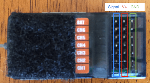
Since I hadn’t use an RC receiver before this project, I wasn’t sure about how the pins of the receiver are wired. Doing a bit of research, I found that the rightmost row of pins are ground pins, the middle row are V+ pins, and the leftmost row of pins (closest to the labels) are the signal pins.
Using a multimeter, I found that the V+ and GND pins are all connected together:
What this means is that we need only the following connections:
- a wire connecting arduino GND to any of the pins in the GND row of the receiver
- a wire connecting arduino V+ to any of the pins in the V+ row of the receiver
- individual wires for each channel connecting the arduino to the receiver
How the receiver sends data
The receiver transmits data through Pulse Position Modulation (PPM). Roughly every 20ms, the signal pins become high (5v) for between 1ms (1000μs) and 2ms (2000μs). The duration of this pulse indicates the position of the channel’s stick. Check out this article on reading an RC receiver for further explaination.
When the stick is centered, this pulse will be 1500μs in length. When it is at maximum, the pulse will be 2000μs, and when it is a minimum the pulse will be 1000μs. Note that these values can vary slightly depending on the manufacturer of your RC receiver, and how it is configured.
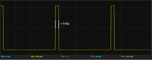
In order to check my understanding of how everything was working, I connected 5V and GND to the receiver, and connected the channel 3 (which I know to be the throttle) signal pin to my oscilloscope.
With the throttle stick all the way at the bottom, I saw that the pulse was approximately 1ms (or 1000μs) in length. Note, each major division on the graph is 5ms.
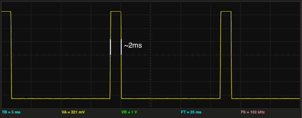
When I raised the throttle stick to the maximum position, I saw that the pulses lengthed to approximately 2ms (or 2000μs) in length:
It seems that the signals look just as expected!
Connecting the Arduino and using EnableInterrupt to trigger interrupts
The general approach that we’ll be using is to set up a CHANGE interrupt on each of the
pins that we connect the signal wires to. This way, functions will be called when the signal
goes high or low. We can use these change interrupts to calculate the time between the
signal going high and the signal going low, and thus get the value.
Because we’re using the EnableInterrupt library, we can use almost any pins that we want. To get an idea of which pins you can use with your particular Arduino, take a look at the EnableInterrupt wiki. For my demo sketch, I connected the Arduino to the receiver as follows:
The Code
Here is the full code for reading the values from the RC receiver. Scroll down for the breakdown and walkthrough.
#include <EnableInterrupt.h>

#define SERIAL_PORT_SPEED 57600
#define RC_NUM_CHANNELS  4

#define RC_CH1  0
#define RC_CH2  1
#define RC_CH3  2
#define RC_CH4  3

#define RC_CH1_INPUT  A0
#define RC_CH2_INPUT  A1
#define RC_CH3_INPUT  A2
#define RC_CH4_INPUT  A3

uint16_t rc_values[RC_NUM_CHANNELS];
uint32_t rc_start[RC_NUM_CHANNELS];
volatile uint16_t rc_shared[RC_NUM_CHANNELS];

void rc_read_values() {
  noInterrupts();
  memcpy(rc_values, (const void *)rc_shared, sizeof(rc_shared));
  interrupts();
}

void calc_input(uint8_t channel, uint8_t input_pin) {
  if (digitalRead(input_pin) == HIGH) {
    rc_start[channel] = micros();
  } else {
    uint16_t rc_compare = (uint16_t)(micros() - rc_start[channel]);
    rc_shared[channel] = rc_compare;
  }
}

void calc_ch1() { calc_input(RC_CH1, RC_CH1_INPUT); }
void calc_ch2() { calc_input(RC_CH2, RC_CH2_INPUT); }
void calc_ch3() { calc_input(RC_CH3, RC_CH3_INPUT); }
void calc_ch4() { calc_input(RC_CH4, RC_CH4_INPUT); }

void setup() {
  Serial.begin(SERIAL_PORT_SPEED);

  pinMode(RC_CH1_INPUT, INPUT);
  pinMode(RC_CH2_INPUT, INPUT);
  pinMode(RC_CH3_INPUT, INPUT);
  pinMode(RC_CH4_INPUT, INPUT);

  enableInterrupt(RC_CH1_INPUT, calc_ch1, CHANGE);
  enableInterrupt(RC_CH2_INPUT, calc_ch2, CHANGE);
  enableInterrupt(RC_CH3_INPUT, calc_ch3, CHANGE);
  enableInterrupt(RC_CH4_INPUT, calc_ch4, CHANGE);
}

void loop() {
  rc_read_values();

  Serial.print("CH1:"); Serial.print(rc_values[RC_CH1]); Serial.print("\t");
  Serial.print("CH2:"); Serial.print(rc_values[RC_CH2]); Serial.print("\t");
  Serial.print("CH3:"); Serial.print(rc_values[RC_CH3]); Serial.print("\t");
  Serial.print("CH4:"); Serial.println(rc_values[RC_CH4]);

  delay(200);
}
You should be able to add additional channels if your receiver supports more than 4.
Note, I probably could have refactored the code to make it a bit more concise, but I wanted to keep it as understandable as possible.
Code walkthrough
To get started with the code, we include the EnableInterrupt library
(you could also use PinChangeInt). We add macros for the number of channels
we have, as well as RC_CH1 - RC_CH2 which will allow us to access the specific
channels in arrays. Finally, we have RC_CH1_INPUT - RC_CH4_INPUT which
define the pins that the signals are connected to.
#include <EnableInterrupt.h>

#define SERIAL_PORT_SPEED 57600
#define RC_NUM_CHANNELS  4

#define RC_CH1  0
#define RC_CH2  1
#define RC_CH3  2
#define RC_CH4  3

#define RC_CH1_INPUT  A0
#define RC_CH2_INPUT  A1
#define RC_CH3_INPUT  A2
#define RC_CH4_INPUT  A3
Next, we declare some arrays. rc_values[] will contain the final values that
we have read, and is intended to be used by our sketch outside of the
RC code. rc_start[] keeps track of the time (from micros()) that the pulses
start.
rc_shared[] holds the values for each channel until they can be copied into
rc_values[]. It is marked volatile because it can be updated from the interrupt
service routines at any time. We don’t want to use this outside of the RC
code exactly because it can be updated at any time.
uint16_t rc_values[RC_NUM_CHANNELS];
uint32_t rc_start[RC_NUM_CHANNELS];
volatile uint16_t rc_shared[RC_NUM_CHANNELS];
Next, we define our interrupts and our setup() function. For
the rest of the walkthrough, I’ll only be showing CH_1 functions. for brevity.
We start by opening a serial port so we can look at the RC values after we’ve read
them, and set the RC_CH*_INPUT pins to INPUT.
We enable an interrupt on the RC_CH1_INPUT pin, so that the calc_ch1
function will be called any time that pin’s value changes from high to low, or vice versa.
void calc_ch1() { calc_input(RC_CH1, RC_CH1_INPUT); }

void setup() {
  Serial.begin(SERIAL_PORT_SPEED);

  pinMode(RC_CH1_INPUT, INPUT);

  enableInterrupt(RC_CH1_INPUT, calc_ch1, CHANGE);
}
Next is the calc_input function, which is where most of the logic resides.
We start out by checking if the pin that changed is HIGH or not. If it is
HIGH, we know that the pulse has just started (e.g. we are on the leading edge of
the pulse). If it is LOW, we know we are at the end of the pulse.
If we are at the beginning of the pulse, we need to store the micros() time at which
the pulse is starting, for later comparison.
If we are at the trailing edge of the pulse, we compare the current micros() to the
value that we previously stored in rc_start[]. The result of the computation indicates
the position of our transmitter stick! We store the value in the rc_shared[] array
for reading later.
void calc_input(uint8_t channel, uint8_t input_pin) {
  if (digitalRead(input_pin) == HIGH) {
    rc_start[channel] = micros();
  } else {
    uint16_t rc_compare = (uint16_t)(micros() - rc_start[channel]);
    rc_shared[channel] = rc_compare;
  }
}
Finally, we have our main loop, which periodically calls the rc_read_values()
function, and then prints out the values for viewing on the serial monitor.
The rc_read_values() function simply copies the volatile rc_shared[] values into
the rc_values[] array. Prior to copying, we disable interrupts to ensure that
the interrupts do not trigger and alter the memory as we’re trying to read it.
Again, the rc_values[] array should be used throughout
the rest of our program (the non remote control related code).
void loop() {
  rc_read_values();

  Serial.print("CH1:"); Serial.print(rc_values[RC_CH1]); Serial.print("\t");
  /// ...

  delay(200);
}

void rc_read_values() {
  noInterrupts();
  memcpy(rc_values, (const void *)rc_shared, sizeof(rc_shared));
  interrupts();
}
If you’ve wired everything, and the program is set up properly, you should see something like the following in the serial monitor:
CH1:1572	CH2:1248	CH3:1076	CH4:1436
CH1:1708	CH2:1096	CH3:1076	CH4:1436
CH1:1704	CH2:1108	CH3:1084	CH4:1424
CH1:1668	CH2:1160	CH3:1372	CH4:1472
CH1:1572	CH2:1352	CH3:1440	CH4:1448
CH1:1528	CH2:1480	CH3:1248	CH4:1364
CH1:1504	CH2:1548	CH3:1072	CH4:1296
CH1:1444	CH2:1420	CH3:1156	CH4:1268
CH1:1496	CH2:1092	CH3:1652	CH4:1456
CH1:1544	CH2:1096	CH3:1772	CH4:1536
CH1:1760	CH2:1204	CH3:1776	CH4:1900
CH1:1840	CH2:1472	CH3:1768	CH4:1912
CH1:1732	CH2:1856	CH3:1776	CH4:1680
CH1:1592	CH2:1852	CH3:1776	CH4:1520
CH1:1496	CH2:1476	CH3:1752	CH4:1436
CH1:1528	CH2:1096	CH3:1088	CH4:1212
Further improvements
That’s it for now, however here are some ideas of how you might further improve the code:
- Add a
last_update_timevariable which gets updated every time an interrupt fires. Iflast_update_timehas not been updated in 2 seconds, consider the receiver disconnected and reset the values to 1500. - Add a constrain call to ensure that the values are within the expected range of 1000μs - 2000μs.
- If the values that are sent by your receiver are not exactly in the range of 1000μs - 2000μs, you may want to add some sort of calibration, perhaps with the arduino map function.
In addition to code improvements, you may want to configure the transmitter itself. Check out the resources below.
Resources
- How To Read an RC Receiver With A Microcontroller - Part 1
- HOW TO: Make your own USB cable for HK-T6A calibration
- Turborix/HobbyKing/Flysky Configurator for Mac OSX
- Transmitter/receiver data sheet
Thanks for reading!
If you have any questions or comments tweet me @bolandrm!
I plan to write some more in-depth posts about building my quadcopter flight controller from scratch. Be sure to follow me if you’re interested!


